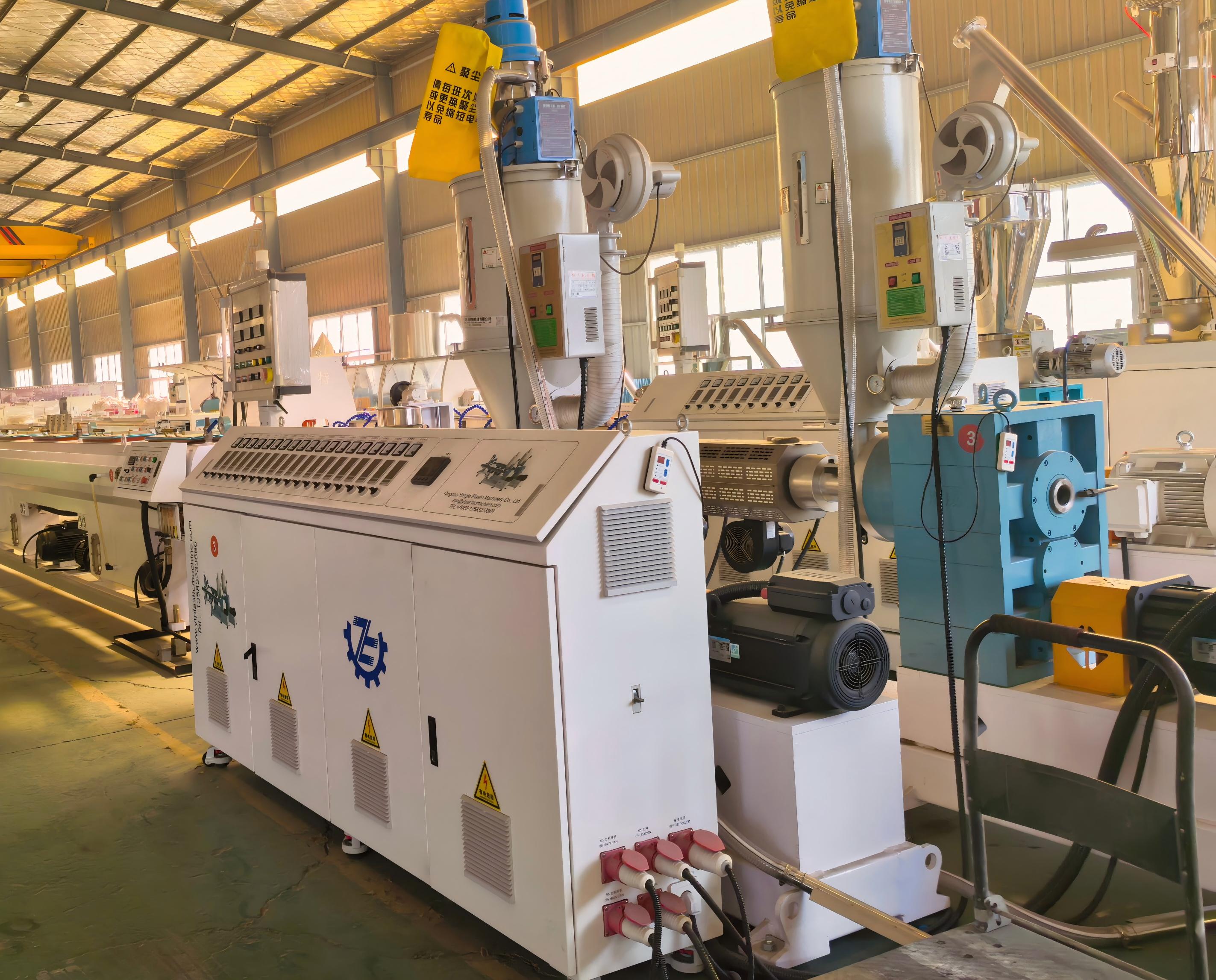

PPR Pipe Machine Solution: A Practical Guide to Efficient Pipe Production
2026-09-25
You can spot a poorly designed PPR pipe line within the first hour of a production run—uneven wall thickness, frequent jams, or output numbers that never quite match the spec sheet. The fix usually isn't more operator training; it's the machine solution itself. In this guide, we look at what separates an efficient PPR pipe machine from a costly bottleneck, and where Yongte fits into that picture.
Why PPR Lines Deserve a Better Machine Setup
Running a PPR line on outdated or poorly calibrated machinery quietly drains productivity. The material behaves differently than standard polyolefins, so pressure spikes, uneven melt temperatures, and inconsistent wall thickness become routine headaches. What looks like a minor tolerance drift on paper compounds over thousands of meters of pipe, turning into scrap, rework, and frustrated operators who end up babysitting dials instead of optimizing output.
A better machine setup starts with three overlooked controls: screw geometry matched to PPR's thermal sensitivity, barrel zone profiles that avoid local overheating, and downstream calibration that holds roundness without excessive drag. When these align, the same line can push higher line speeds while using less energy per meter. Operators stop chasing variance and start seeing stable parison, cleaner cuts, and fewer emergency shutdowns.
The real payoff shows up in long production runs and hidden costs. Proper setup reduces wear on screws and barrels, extends calibration sleeve life, and cuts the frequency of die buildup cleanings. It also frees engineers to focus on new profiles or color changes rather than firefighting the same extrusion defects every week. For any shop serious about PPR, the machine is not a fixed constraint—it is the easiest lever to pull for better margins.
Matching Extruder Output to Your Daily Production Targets
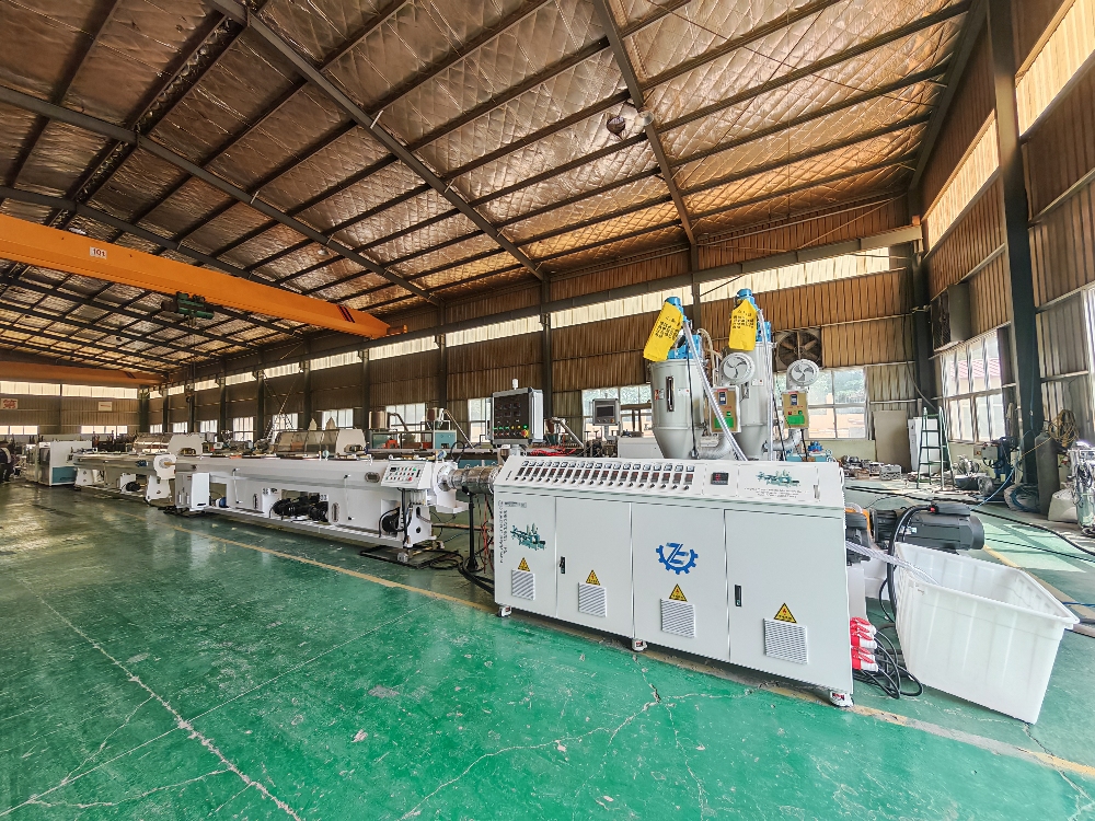
Getting daily targets right with an extruder often comes down to understanding how screw speed, melt temperature, and feed rate interact. Instead of treating the machine as a fixed device, run a short calibration batch at the start of each shift. Record output weight over ten minutes and compare it to what your plan actually requires. Small adjustments here can prevent you from overproducing by mid-morning or scrambling to catch up after lunch.
It also helps to break the day into two or three windows rather than chasing a single number. If your target is 400 kilograms, check whether you are hovering near 200 by the midday break. That gives you room to tweak throughput without risking a quality drop. Keep an eye on how material viscosity shifts with ambient temperature, especially in older facilities; a cooler floor in the morning can quietly reduce output even when settings stay the same.
Finally, match your downstream equipment to the extruder pace. A slight mismatch at the cutter, puller, or cooling bath often forces operators to dial back speed in ways that are not obvious on the control panel. Walking the line once per shift and asking where bottlenecks sit usually reveals a simple fix that brings daily output in line without pushing the screw beyond its efficient range.
The Calibration Sleeve and Cooling Decisions That Shape Pipe Quality
Pipe dimensions are largely locked in the moment the extrudate enters the calibration sleeve. The sleeve's internal diameter, vacuum slot pattern, and surface finish determine how uniformly the hot polymer is drawn against the cooled wall. A sleeve that runs too cold can chill the outer skin before the melt has fully conformed, leaving micro-voids or a rippled surface. Conversely, if the sleeve runs warm or the vacuum pull is uneven, the pipe may develop slight ovality or diameter drift along the line.
Cooling after the sleeve is just as decisive. Laying the pipe through graduated water baths with a controlled temperature profile lets the wall cool from both sides at a rate that limits residual stress. When one side of the pipe sees colder water or a stronger spray, differential shrinkage curves the product or builds in stress that later shows up as cracking at fittings. Some processors keep the first quench tank only a few degrees below the sleeve temperature, then step down gradually to avoid freezing in a brittle outer layer.
The real skill is matching sleeve temperature to downstream cooling intensity. A short, cold sleeve with aggressive water quench may run fast, but it often produces pipe with high surface gloss and a stressed inner wall. A longer sleeve with warm water circulation and a moderate pull gives the melt more time to stabilize, which improves roundness and reduces split failures during pressure testing. Operators who monitor pipe sag between the sleeve exit and the first support roller can adjust either the sleeve vacuum or the initial quench temperature to keep the product consistent hour after hour.
Avoiding the Common Material Feeding and Melt Pressure Mistakes
Many processors assume material feeding problems start and end with a dirty hopper, but the real culprits are often subtle variations in bulk density, pellet size, or regrind ratio. If you don't control how material enters the screw, you'll chase pressure fluctuations endlessly. Keep hopper levels consistent, use proper drying hoppers, avoid bridging with low-angle hoppers or vibrators, and make sure the feed throat stays cool enough to prevent premature melting.
Melt pressure is more than a number on a gauge; it's a direct read on how the screw is building and maintaining melt quality. A common mistake is ignoring upstream pressure variation and only looking at the nozzle. If you don't monitor pressure at the screw tip or before the check ring, you won't catch leaks, worn screws, or poor mixing until parts are out of spec. Set realistic back pressure based on resin: too low lets unmelted pellets through, too high adds shear heat and degrades material.
Another overlooked mistake is failing to correlate feed stability with melt pressure trends. When feed is erratic, melt pressure will oscillate, often showing as periodic dips or spikes on a pressure trace. Instead of cranking up barrel temperatures to compensate, stop the line and verify actual feed rate, screw recovery time, and hopper loading. Use pressure data as a diagnostic, not just a limit alarm.
Cutting, Hauling, and Stacking Without Damaging Finished Pipes
When moving finished pipe around the yard, the easiest way to invite trouble is to treat it like raw stock. A single drop onto a hard surface or a quick drag across concrete can leave scratches that become stress risers later. Use padded cradles or slings that spread the load, and keep fork tines away from the pipe body unless they have smooth, non-metallic guards. For smaller diameters, hand-carry with two people rather than letting one person balance a long length on a shoulder.
Cutting should happen on a stable, well-supported setup. If the pipe is allowed to sag or vibrate during the cut, the finished coating or threads can get chewed up at the clamp points. Wrap the contact areas with rubber or old conveyor belting, and tighten just enough to hold position, not enough to dent. Let the saw do the work without forcing it; excessive feed pressure generates heat and leaves a ragged edge that requires extra cleanup and can compromise the end finish.
Stacking is often where hidden damage shows up later. Use dunnage that is clean, dry, and free of nails or grit, and line it up so the load transfers straight down through the spacers. Keep layers separated with material that won't trap moisture against the pipe surface. If you're stacking different sizes, put the larger, heavier pieces at the bottom, and chock the ends to prevent rolling. A little extra time spent on the stack keeps the pipe round and the coating intact until it reaches the trench.
Fine-Tuning Line Speed, Temperature Zones, and Wall Thickness Consistency
Adjusting line speed is rarely just about pushing more output. When the haul-off runs too fast, the outer skin sets before the inner wall has stopped flowing, and the thin spots show up first—usually opposite the weld line. A practical approach is to lock the screw speed, then change the puller speed in steps of half a percent while recording wall thickness at four points around the circumference with an ultrasonic gauge. Don't touch two variables at once, or the cause of any drift becomes guesswork.
The gradient between temperature zones matters more than the absolute setpoints. An overheated feed zone shifts plasticating earlier into the screw, which makes the metering section hunt and wall thickness oscillate along the length. Use an infrared gun to check actual barrel temperatures instead of trusting the panel display. If the wall reads thin right at the weld line, the problem often isn't the die—it's a cold slug sitting at the interface between zones, disrupting melt pressure just enough to leave a mark.
Wall thickness consistency should only be judged after the line has run stable for at least twenty minutes. Startup readings are noise because the thermal profile hasn't settled. A simple routine works better than constant fiddling: measure once every fifteen minutes, and don't adjust anything until three consecutive readings stay within 0.05 mm of each other. Otherwise you end up chasing your own corrections and the line never finds a steady state.
FAQ
Start with your target output range and pipe diameter span, then look at screw design and torque. A machine that struggles to maintain melt homogeneity at higher throughput will create wall-thickness drift and waste. Check whether the vacuum calibration tank has enough length for the speeds you plan to run, and confirm the haul-off and cutter can handle short pipe lengths without deforming the ends.
Drying is often skipped because PPR is not highly hygroscopic, but even low moisture can create surface blemishes and internal voids at high output. Use a dedicated resin handling system, keep regrind below 10-15% unless you validate higher levels, and make sure the hopper loader does not introduce temperature swings into the extruder feed zone.
Running the screw at maximum RPM without adjusting barrel temperatures, ignoring pressure build-up before the screen pack, and letting calcium carbonate build-up in the calibration sleeves are frequent culprits. Scheduled checks of die land wear and drive motor current can prevent sudden stops during long production campaigns.
PPR has a narrow processing window. If melt pressure oscillates, you get periodic wall thickness variation, poor inner surface quality, and higher scrap at the socketing stage. A stable pressure profile also means the downstream sizing and cooling can be tuned once and left alone, which directly affects output consistency.
The calibration sleeve sets the outer diameter immediately after the die, while the vacuum tank locks the roundness before the pipe cools below the crystalline transition. If the water temperature is too low or the vacuum level is inconsistent, the pipe can become oval or develop shrinkage marks. A longer cooling bath is worth the floor space when pushing diameters above 63 mm.
Look for closed-loop control of barrel temperatures and haul-off speed rather than full plant automation from day one. Automatic die centering and ultrasonic wall-thickness scanning reduce operator dependence and catch drift early. The goal is to keep one operator able to manage two lines, not to add screens that require constant babysitting.
Check screw and barrel wear every 1,500-2,000 hours, replace filters and breaker plates before pressure drop exceeds 20%, and calibrate the haul-off and cutter encoders quarterly. Cleaning the vacuum tank strainers and checking vacuum pump seals weekly prevents most quality complaints tied to improper cooling.
Energy per kilogram usually drops as output increases because the base load of drives and heaters is spread over more material, but only up to the point where melt quality starts to suffer. Pushing beyond the screw's optimal RPM range can raise specific energy because regrind or degradation increases and downstream rejects climb.
Conclusion
Getting a PPR pipe line to run consistently well is less about the extruder's brand name and more about how the entire setup is arranged. Many plants settle for off-the-shelf configurations that leave throughput on the table, which is why a machine layout built around your specific daily output target matters far more than raw screw diameter. Once the extruder's output is matched to the haul-off speed and downstream capacity, the calibration sleeve becomes the real quality gate. A sleeve that is too short or cooled unevenly will force you to run slower or accept ovality and surface defects. Cooling decisions, from vacuum tank water temperature to spray nozzle placement, directly determine whether the pipe wall stays round and free of internal stress. Treat these elements as one interconnected system rather than isolated parts, and you eliminate most of the trial-and-error that plagues start-ups.
Beyond the die, the way material enters the extruder and builds pressure is where hidden inefficiencies live. Bridging, inconsistent pellet feed, or running the barrel zones too hot can cause surging that shows up later as dimensional drift. Keep melt pressure steady by adjusting screw speed in small steps and by verifying that the feed throat stays cool enough to avoid premature melting. At the end of the line, cutting, hauling, and stacking equipment often gets overlooked until it scratches or dents finished pipes. Use synchronized haul-off with soft-contact clamps and stack pipes on flat, debris-free racks. Finally, fine-tuning line speed and temperature zones should be done together: a faster line speed requires a slightly higher melt temperature and a longer cooling path, but only up to the point where wall thickness consistency begins to suffer. Check wall thickness at multiple points around the circumference after every speed change, and you will find the narrow operating window where output and quality both hold.
Contact Us
Contact Person: Ms Qin
Email: [email protected]
Tel/WhatsApp: 8613583233866
Website: https://www.yongteplast.com